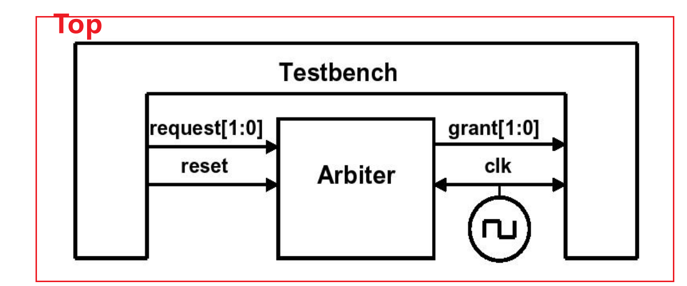
Testbench Architecture & SystemVerilog interface
- SystemVerilog
测试平台和DUT连接实例
-
clk需要在顶层top生成(均根据spec来写clk)
-
tb产生激励给到DUT,DUT输出结果返回到tb
从以上这个例子中初步体会到SV验证模块化的好处(强调重复性),因为在Verilog中是针对每一个rtl都写一个对应的tb来验证。
使用端口的仲裁器模型DUT
module arb_port(output logic [1:0] grant,
	output logic grant_valid,
	input logic [1:0] request,
	input logic rst,
	input logic clk);
    ...
使用端口的测试平台TB
可以看到port list(端口列表)如果数据量大会非常复杂和繁琐
module test(input logic [1:0] grant,
	input logic grant_valid,
	output logic [1:0] request,
	input logic rst,
	input logic clk);
initial begin
    ...
顶层连接
- rtl和tb中出现的校核信号都需要在顶层中声明
- clk信号需要在top中声明(第五行)
module top;
	logic[1:0]grant, request;
	logic grant_valid;
	bit clk,rst;
	always #5 clk=~clk;
arb_port a1(grant, grant_valid, request, rst, clk);
test t1(grant, grant_valid, request, rst, clk);
endmodule
这种方法的缺点就是若DUT arb_port的端口需要改变,在test和top中的声明都要改变。在真实的设计中, 往往含有数百个端口信号,因此,sv中推荐使用一种interface的结构。
SV的interface
SV使用接口来连接不同模块。接口可以看作一捆智能连线,连接了DUT和验证平台。
- interface中只需定义几个模块间所有需要交互的信号
- 无需定义clk,因为对于几个模块来说,clk都是input,所以在portlist里就将其定义
interface arb_interface(input bit clk);
	logic[1:0] grant,request;
	logic grant_valid;
	logic rst;
endinterface
使用接口的仲裁器
module arb(arb_interface arbif); //接口名,例化名。把接口当作整体
…
always@(posedge arbif.clk or posedge arbif.rst);
begin
	if(arbif.rst)
	arbif.grant <= 2’b00;
else arbif.grant <= next_grant;
…
end
endmodule
module test(arb_interface arbif);//tb
…
initial begin
…
@(posedge arbif.clk);
arbif.request <= 2’b01;
$display(“@%0t: Drove req=01”,$time);
...顶层:clk同样在top层定义,连接时也有些许区别(接口作为整体的信号传递进dut和tb)
- 多了例化接口步骤
- 多了连接DUT和tb的步骤,且过程极大简化了,无需再在其中重复声明变量
module top;
	bit clk;
	always #5 clk=~clk;
    arb_interface arbif(clk);//例化接口,把clk信号传进去
    arb a1(arbif); //连接DUT,接口作为整体的信号传递进去
	test t1(arbif); //连接tb
endmodule:top
modport
在上述的例子中并没有对接口内的信号指定方向(logic性质)
使用modport将接口中的信号分组tips
定义方法:modport 模块名(input XXX,output xxx)
- modport定义在interface中
- modport中无需定义位宽,其中只需声明传输方向
- 模块名不一定要和tb/rtl完全相同
- modport括号中没有分号,使用的是逗号
interface arb_if( input bit clk);
	logic[1:0] grant,request;
	logic rst;
	modport TEST(output request, rst,
				input grant, clk);
	modport DUT(input request, rst, clk,
				output grant);
	modport MONITOR(input request, grant, rst, clk);
endinterface
所以module定义的时候端口例化就变成:(原来是arb_if arbif)
module arb( arb_if.DUT arbif);  //接口名.modport名
...
endmodule

module test(arb_if.TEST arbif);
endmodule

module monitor(arb_if.MONITOR arbif);
endmodule
接口中clocking block
//interface
interface arbiter_interface(input bit clk);
logic [1:0] grant,request;
logic       grant_valid;
logic       rst;

//input and output are defined from a tb perspective
clocking cb @(posedge clk); // Declares a clock module cb
        input grant, grant_valid, clk;
        output request;
endclocking

modport DUT_arbiter (input request, clk, rst,  //注意clk在tb和dut中都是input
                     output grant, grant_valid);
modport tb_arbiter (clocking cb,  //调用cb
                     output rst);
modport monitor(input request, grant_valid, cb.grant, rst, clk);
endinterface
module tb_arbiter(arbiter_interface.tb_arbiter arbif);
initial begin
@(arbif.cb) arbif.cb.request <= 2'b01;//在时钟的上升沿(posedge)触发时执行,将request信号设置为2'b01
$display("@%0t : Drove req=01",$time);
repeat(2) @(arbif.cb) //在时钟的上升沿触发时,重复执行后续的代码两次。
if(arbif.cb.grant != 2'b01)
$display("@%0t : grant != 2'b01",$time);
end
endmodule接口interface的优缺点
- 优点:(自己的话概括)
- 便于设计重用;
- 可以替代原来需要在模块或者程序中重复声明并且位于代码内部的一系列信号,减少连接错误的可能性
- 要增加一个新信号时, 只需要在接口中声明一次, 不需要在更高层的模块层声明, 进一步减少错误;
- modport允许一个模块将接口的一系列信号捆绑到一起, 为信号指定方向;
- 缺点:(较少考察)
-
对于点对点的连接, 使用modport跟使用信号列表的端口一样冗余;
-
必须同时使用信号名和接口名,会使模块变得更加冗长;
-
如果连接两个模块使用的是一个不会被重用的专用协议,使用接口需要做比端口连线更多的工作;
-
连接两个不同的接口很困难;一个新的接口可能包含了现有接口的所有信号并新增了信号,需要拆分独立的信号并正确的驱动;
接口的驱动和采样
接口同步
用verilog的@和wait来同步测试平台中的信号.
//接口中的时钟块
clocking cb@(posedge clk)
    	input grant;
    	output request;
endclocking

program automatic test(bus_if.TB bus);
	initial begin
		@bus.cb; //clock模块中时钟的有效沿触发
		repeat(4) @bus.cb; //等待4个有效时钟沿
        @bus.cb.grant; //监测grant信号的变化(上升,下降),由接口中的cb触发的grant信号
		@(posedge bus.cb.grant); //监测grant信号的上升沿
		@(negedge bus.cb.grant); //监测grant信号的下降沿
		wait (bus.cb.grant==1); // 监测一个电平值, 若监测不到, 则一直等待
		@(posedge bus.cb.grant or negedge bus.reset); //思考:这个是等待什么?
	end
endprogram
接口信号采样
test对clocking cb中的输入信号grant进行采样
module arb(arb_if.DUT arbif);
initial begin
arbif.grant = 1; // @ 0ns 此处驱动没有走cb
#12 arbif.grant = 2; // @ 12ns 为避免冒险所以加了#
#18 arbif.grant = 3; // @ 30ns
end
endmodule
clocking cb @(posedge clk);
output request;
input grant;
endclocking
program test(arb_if.TEST arbif);
initial begin
$monitor("@%0d: grant=%h", $time, arbif.cb.grant); //cb数据采样
#50;
end
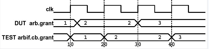
endprogram图片可观察到在30ns处,DUT的grant的值在时钟沿跳变,同时TEST的cb.grant也在该时钟沿触发输出,但此时它采样的值还是该时刻之前的值2,这就是由于dut的驱动未走cb来驱动所造成的
- ps:dut是12、30ns处发生变化,而cb.grant是每次时钟上升沿而触发一次,这样就会造成取值与实际不一致的情况
接口信号驱动
program test(arb_if.TEST arbif);
	initial begin
		# 7 arbif.cb.request <= 3; // @ 7ns
		#10 arbif.cb.request <= 2; // @ 17ns
		#13 arbif.cb.request <= 1; // @ 30ns
		#15 $finish;
	end
endprogram

module arb(arb_if.DUT arbif);
	initial
		$monitor("@%0t: req=%h", $time, arbif.request);
endmodule
波形图省略。
30ns处arb.cb.request的变化立刻在上升沿被传送到arb.request上。因为在clocking block中输出信号的默认延迟为#0,软件在编译时, clocking block中的输出信号要晚于被采样信号的变化,但在波形上观察不出来。
驱动和采样总结,在clocking block中,采样(input)和驱动(output)信号遵循如下原则:
- 在clocking block中,“同步后”的采样信号指的是在时钟信号的作用下采样(读取)的信号值。因
为在时钟信号的驱动下进行采样,所以采样得到的信号值是在前一个时钟周期内保持的值,即上一
个状态的值。
- 而“同步后”的驱动信号指的是在时钟信号的作用下进行的驱动(写入)操作,即将信号值输出到
外部。因为在时钟信号的作用下进行驱动操作,所以输出的信号值是当前时钟周期内的值,即当前
状态的值。
因此,以上接口驱动和采样的例子的目的在于意识到在数字系统设计中,信号取值的一致性不仅仅取决于简单地接入时钟信号,还需要考虑时序问题、时钟域之间的同步等复杂因素。只有全面理解了这些因素,才能设计出稳定可靠的数字系统。
附:SV中新增的三个always语句块
always_comb//组合逻辑:主要用于描述纯组合逻辑行为,提供了一种明确的方式来指示逻辑的特性

always_ff; //寄存器:主要用于描述严格的时序逻辑,敏感列表必须是时钟信号(posedge 或 negedge)以及可能的异步复位信号。

always_latch;//锁存器注意:无论是哪种always,都只可写在module或者interface中,不可写在program和class中
Discussion
Loading comments…
Checking sign-in…